Atreum Lighting LED Board Wiring Guide

This guide details how to wire up the Atreum Lighting LED boards in single- and multi-board configurations. The information below is for design purposes only, and is not a safety guide. Please use proper electrical handling techniques when working with live circuits.
Table of Contents
- Background
- Parallel Wiring
- Series Wiring
- Connecting Power Cords to Meanwell LED Driver
- LED Module DC Input Wire Colors
Background
In general, Atreum boards are designed such that all positive terminals are connected to each other, and all negative terminals are connected to each other. What this means is:
- It doesn't matter which (+) or (-) terminal the wiring is connected to.
- Daisy-chaining boards by connecting the positive terminal of one board to the positive terminal of the next board connects the boards in a parallel configuration.
- Daisy-chaining the boards by connecting the negative terminal of one board to the positive terminal of the next board connects the boards in a series configuration.
Parallel Wiring
Two Boards

Three Boards

Four Boards

Five Boards

Six Boards

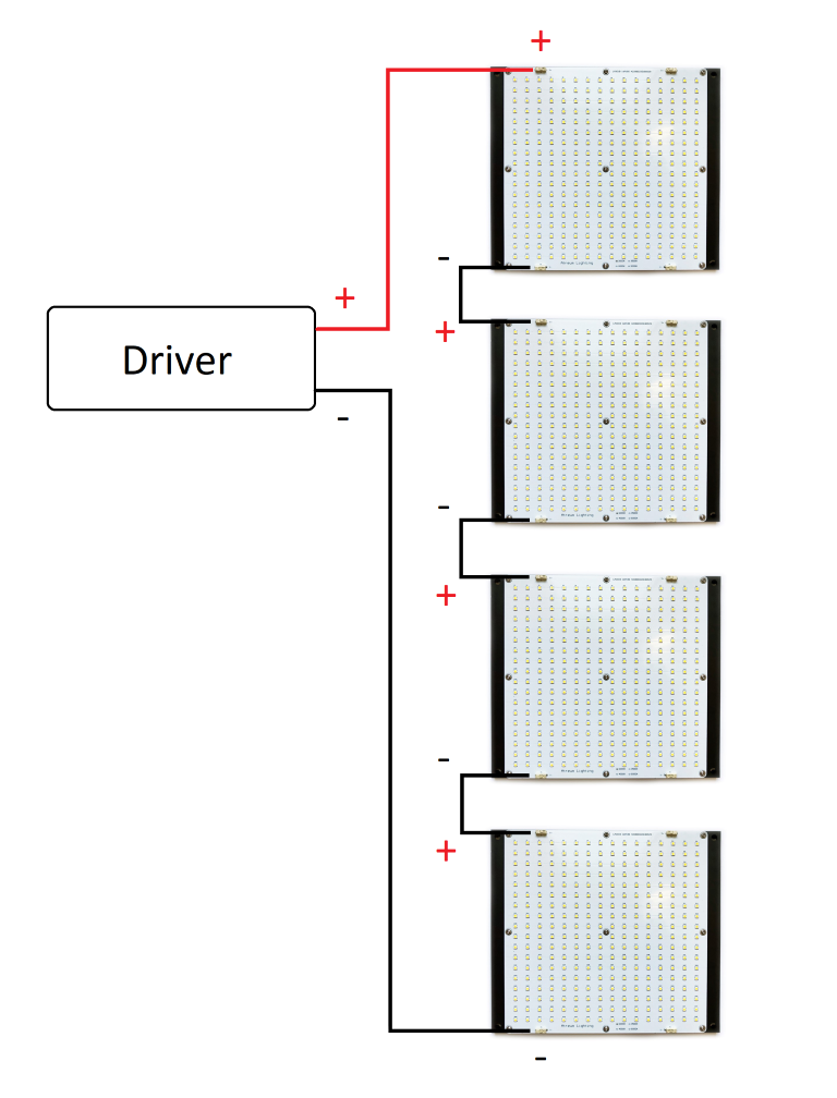
Series Wiring
The diagram below shows four boards wired in series. Boards can be added or removed as desired.
Connecting Power Cord to Meanwell LED Driver Input
We recommend connecting the Power Cord to LED Driver Input using a 2-Way Junction Connector. The corresponding wire colors are detailed in the following table:
| Function | Power Cord Wire Colors | Meanwell LED Driver Input Wire Colors |
| Protective Ground | Green or Green-Yellow | Green or Green-Yellow |
| Neutral (N) | White | Blue |
| Line (L) | Black | Brown |
When tightening down the junction connector screws, ensure the screws are biting on the metal core of the wire.

LED Module DC Input Wire Colors
| Polarity | DC Input Wire Color | Alternate Color |
| Positive (+) | Red | Brown |
| Negative (-) | Black | Blue |